
Wow, things have been going pretty good with this SMPS project. A lot of things are moving forward. I picked up a cabinet that I can use to house the power supply. I also received the 3 printed circuit board designs back from OSH Park this week and started building the PWM controller, drivers and primary filter board. All of the news is below.
Cabinet
I went down to the surplus shop this week to look for a cabinet to put the power supply in. I had a couple of options, the first was an old Tektronix modular oscilloscope case, it still had all the modules in it, etc, but it was old enough that I wouldn’t have felt bad parting it out. The other option was a cabinet from an Hewlett-Packard 3498A expander system. The HP3489A was about $10 cheaper so I went for that instead at $15. If anyone needs parts from an HP3498A let me know I have some various parts.
Here are some photos of this cabinet.
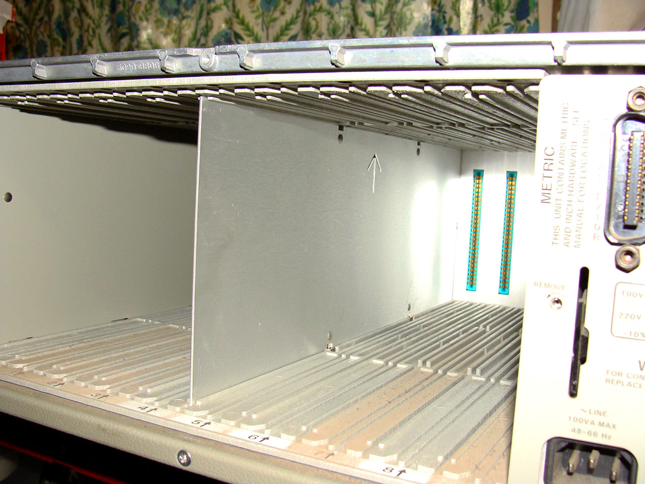
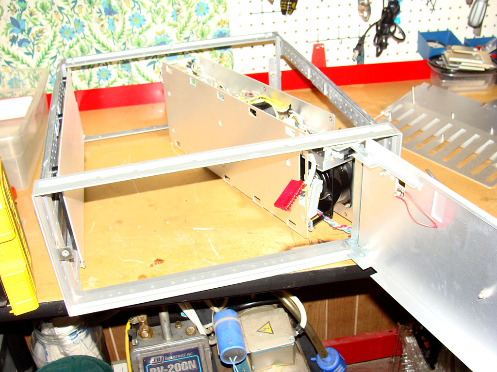
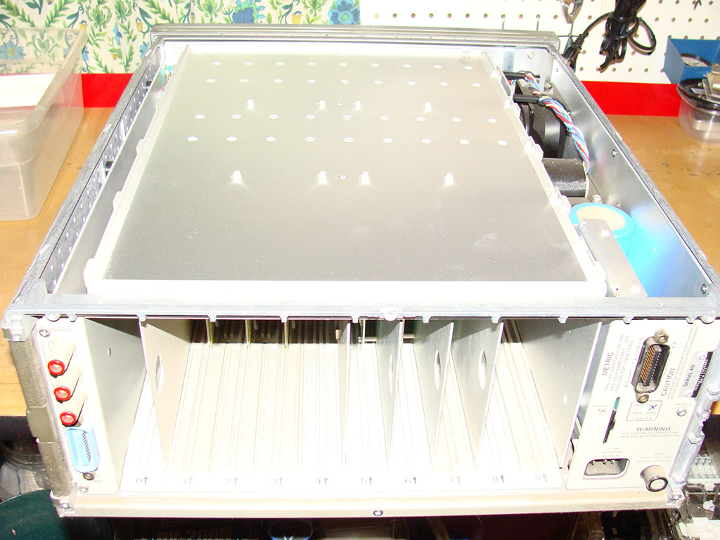
The paint on the cabinet is really ugly, it’s beige, tan and brown. I’ve cleaned the heck out of the side panels and plan on using a 2 part catalyzing spray paint from Eastwood to paint the cabinet satin black, it should improve it’s looks quite a bit right there.
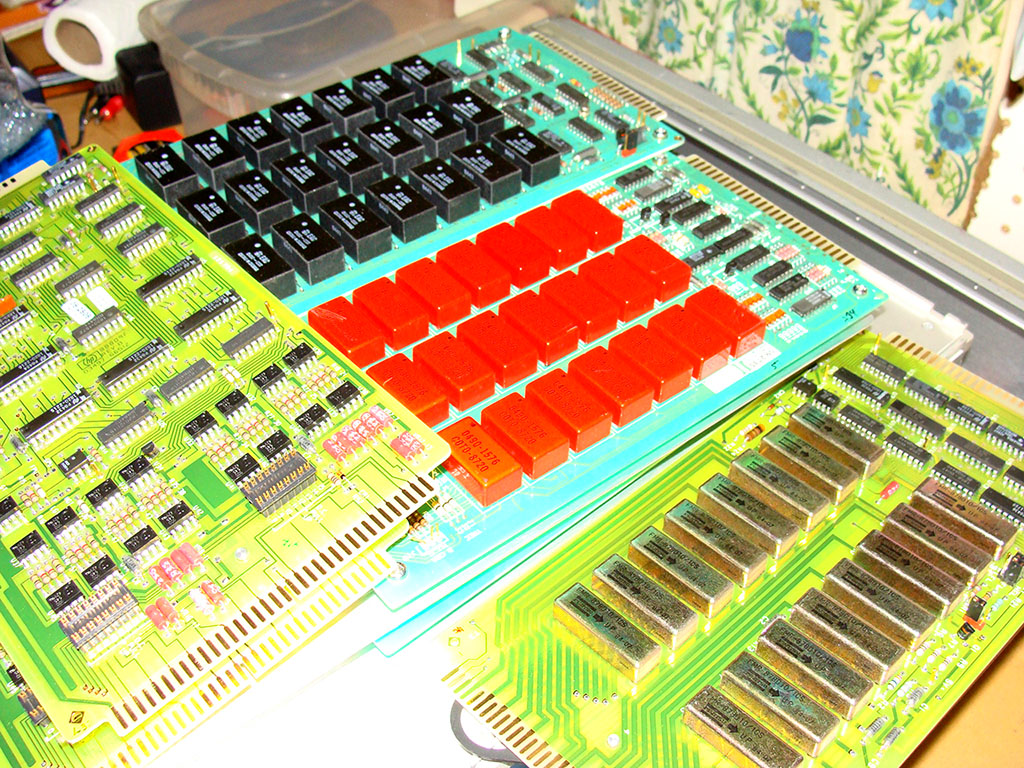
These boxes have a ton of modules with filters, relays and other things, all gold plated and such, but probably not a lot of gold in total to make them worth stripping down and recovering, but some nice looking boards anyways. If you need parts for your A3498A let me know.
PWM Driver Board
The first board to come in was the PWM driver board. I had paid for priority shipping on it, so even though it was made last, I got it first in the mail. The filter and power boards were done first but came in a couple days after the PWM. Here’s a photo of the bare PWM board with no components on it. It turned out pretty nice, but it’s fairly large so it was expensive to have made, and error would be pretty expensive, though if everything works right, I do have 2 spares now.


I had most of the components I needed to populate the pulse-width modulating driver board. I still need to order some connectors and some bridge rectifiers, but that will have to wait until the end of this coming week unless my HP 5385A Frequency Counter sells on eBay.
This is a double sided board so I was going to have to hand solder some surface mount components anyways, I didn’t bother with the toaster oven reflow and soldered everything by hand, so the board looks less than incredible, but it should be fine.
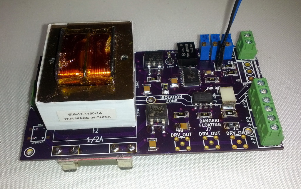

I’ve installed some 10 turn potentiometers for bench testing as you can see in the upper right hand corner of the board. Once this is put inside of the cabinet they will be connected to potentiometers on the front face of the cabinet as needed. The potentiometers set the idle voltage, current and driver gain.
I also put the fuse holders on the bottom, they were too close to the transformer, and since these are floating at hundreds of volts I chose the safer option and moved them to beneath the board.
Filter Board
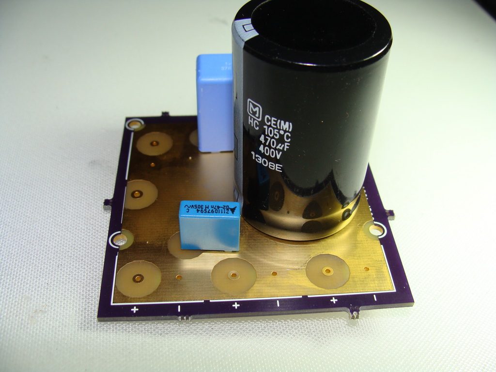
Not much to say about this one that the picture can’t summarize. I designed it without silkscreen over the main area. I just wanted bare exposed copper/gold finish. The boards look good, I had to double check the polarity on the electrolytic capacitor since there are no silkscreen marking in the middle.
I’m still missing the connectors, those will come in next week once I get my next (and hopefully final) order for electronic components taken care of.

Power Driver Boards
This switch mode power supply design is nice in that it’s modular. For each power board used, the PSU can handle around 12-15 amps. I am aiming, initially, to pull about 30 amps peak, so I’ve assembled 2 power driver boards. Each board get’s it’s own large inductor.
The bare boards, like the rest of the stuff I’ve gotten from OSH Park look excellent, and I’m happy with my design decisions I’ve made in the board layout once they show up and I see how things have turned out.
Here are the bare boards
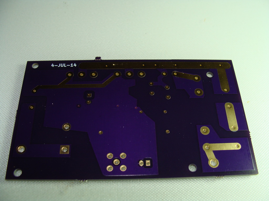

I was able to populate most of the components, but I’m still missing a few connectors, I may bypass the connectors and go with soldering the wires directly to the board. I left the option to do that by adding some extra holes on the board. It would reduce the overall wire length and connector resistance so it may be a good idea.
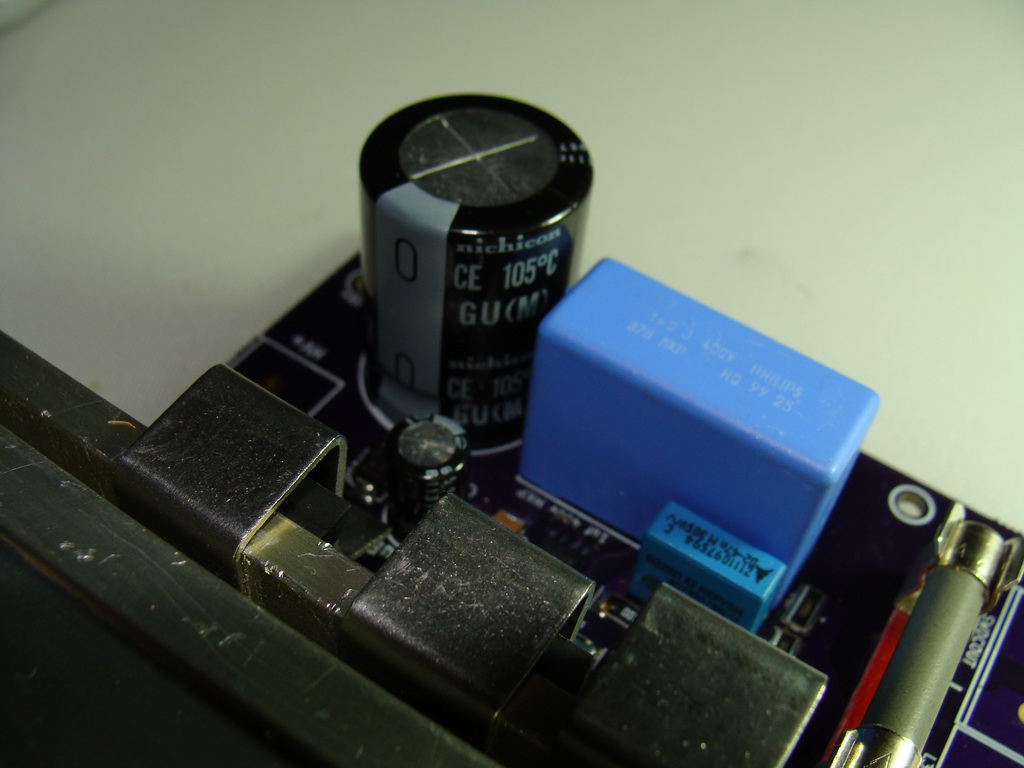
The diode and the MOSFETs are mounted to the heatsink block with only those steel spring clips. They’re very strong. I got the heatsinks and clips out of another SMPS PSU I found at the surplus shop and stripped down for parts. It’s a little crowded so it’s hard to see everything in there. The fuses also came from the scrapped SMPS. I paid $7 for the board and pulled a nice 37.5 amp current shunt off it, these heatsinks, and 2 high value ceramic fuses which are pretty expensive so I did alright.
I also used high quality new Nichicon electrolytic capacitors on this board and the blue caps are also good brands (Phillips for the big one, EVOX for the smaller ones)
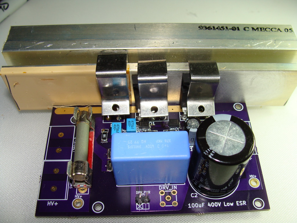
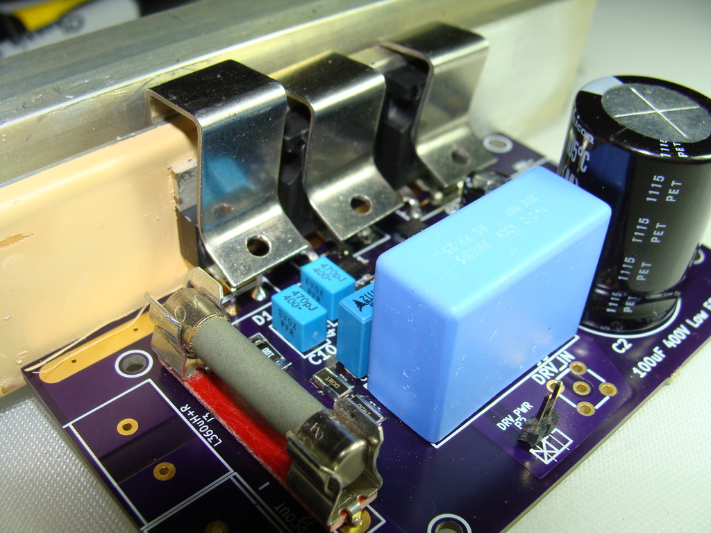
The last thing I’ve done this weekend is to add some flying leads to the inductors, no big deal, but they look nice.

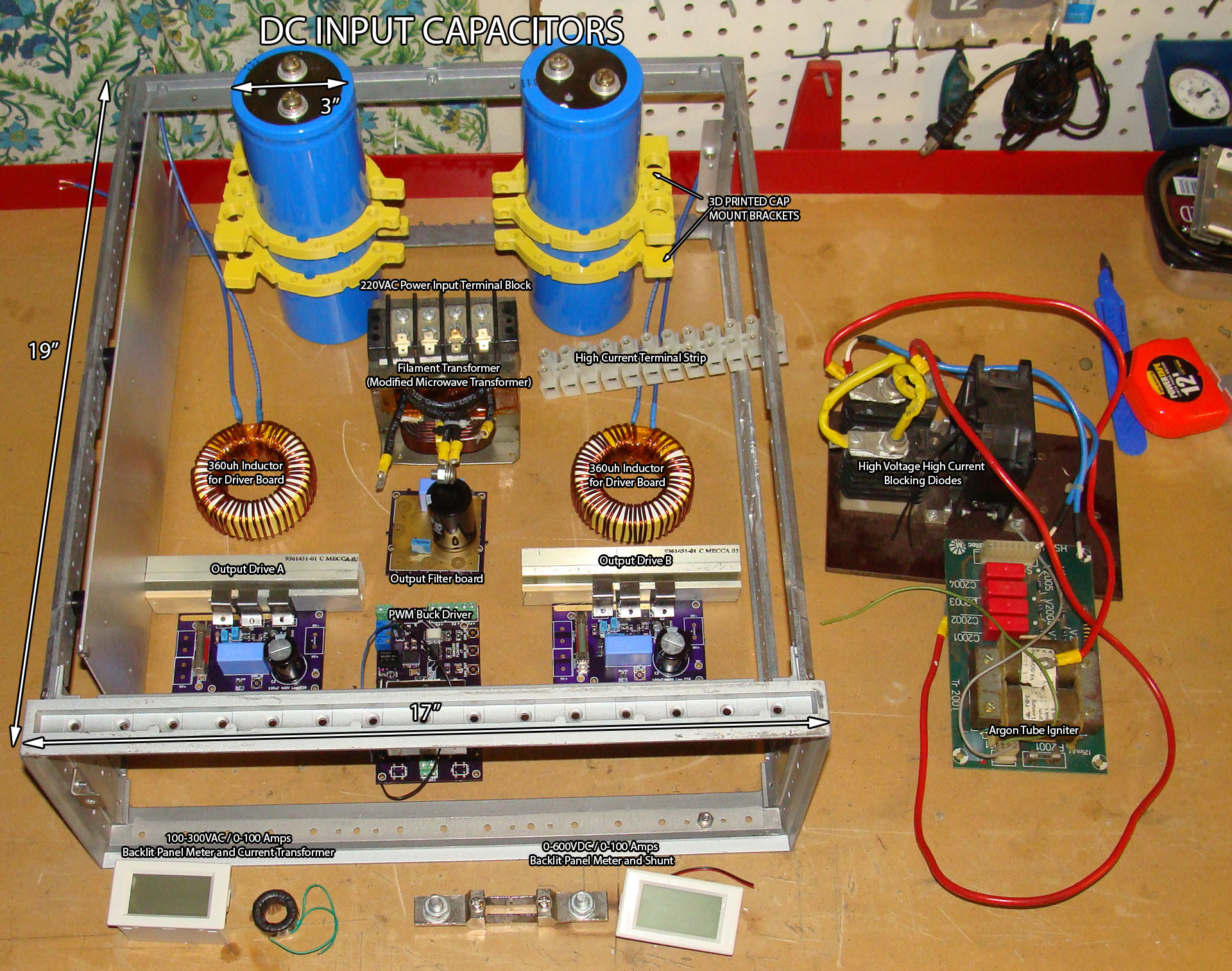
I’ll leave you with a layout of most of the components so far (excluding the laser tube itself) for you to look at, click to enlarge. Thanks for reading, if you like this kind of stuff, please consider sharing it.
Leave a reply to Large Switched DC Power Supply For Argon Laser Project Log 4