If you’ve been following along in my previous post on my Large Switched DC Power Supply (Log 1, Log 2) then you know what has gone on with the project so far. Progress on the argon laser DC power supply is slowly advancing, any good project can take a while when working under budget and time constraints, so please bookmark and make sure to check back occasionally for new updates. I do take a lot of photos which makes these posts very image heavy, but I think it’s a good way to convey information.
I’ve been hard at work designing the circuit boards that will contain most of the necessary components for this project. They’re the PWM Driver Board, the Power Board and the Output Filter Board. I did some 3D renderings of the PWM driver board to see what it will look like when it’s assembled, and I’ve attached them below. I think they turned out pretty good, have a look!
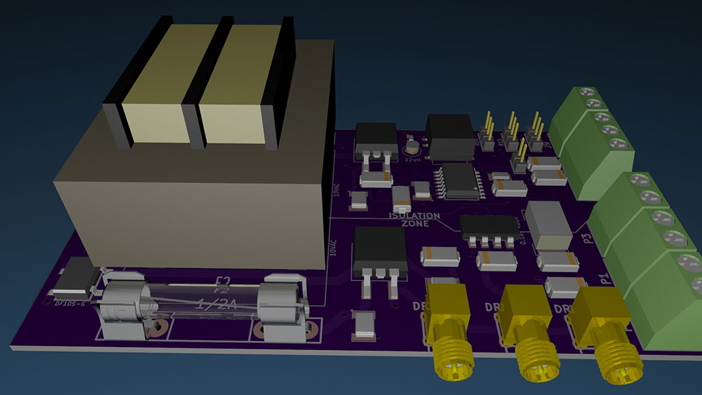

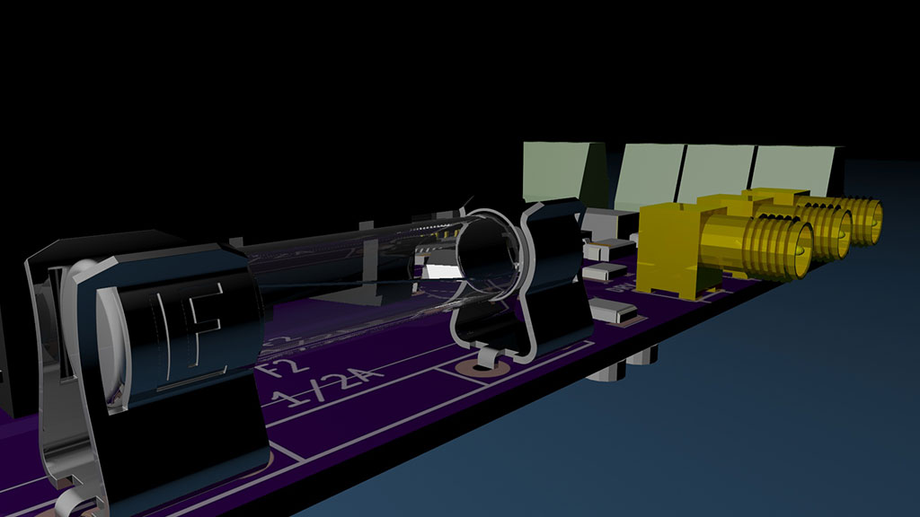
To make these images I exported the circuit board from PCBNew (the Kicad PCB Editor) to a 3D model (.stl) and then imported it into 3D Studio Max 2015 (trial version). I then sent the board gerber files to OSHPark for a price estimate, as part of the process they render what they think the unpopulated PCB will look like when it’s done. I took those renderings and used the for them front and back textures of the printed circuit board. While it’s not convincingly real, it has that marketing appeal and it does give a very good idea of what the finished board will look like. I also rendered a quick video panning around the board, just for fun.
Within a couple of weeks I should have the boards off to production. I’d have them done sooner but ran into something that ate all the funds for PCB board production this month.
Argon ion lasers work similar to a a vacuum tube without a grid plate. They have an anode, and they have a heated cathode or filament, also known as a thermionic emitter. When it’s hot, the filament release or ‘boils off’ ions into the vacuum. With a large high power tube like this argon laser requiring about 25 Amps at 170VDC the emission surface must be quite large, which means a large filament. If you’d like to know more about how the thermionic process works, you can look up thermionic emission on Wikipedia.
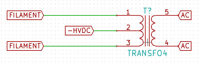
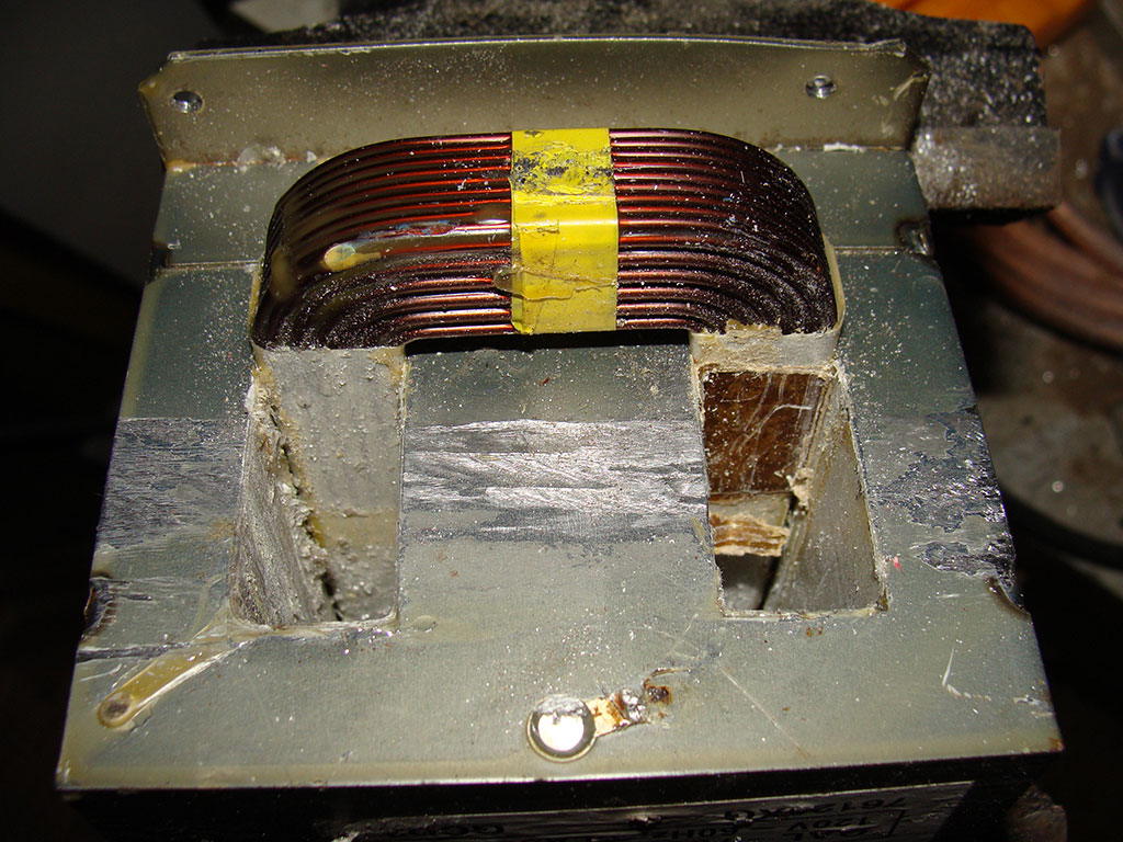
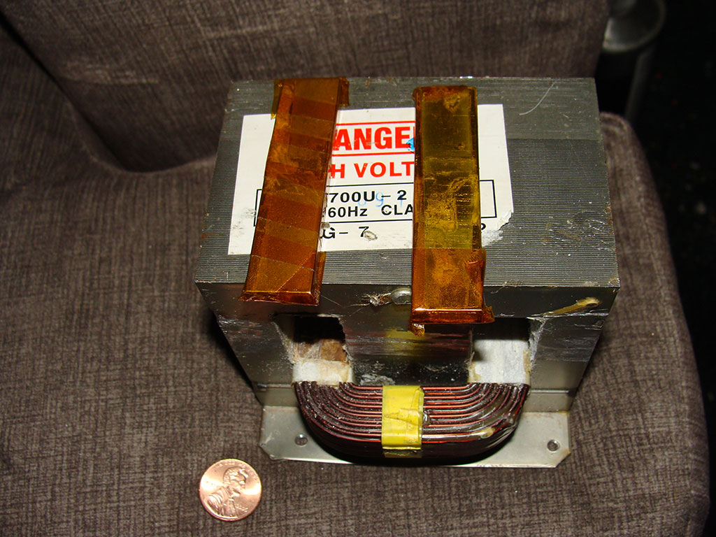
To get such a large filament up to the proper temperatures takes around 75 watts of power. The voltage will vary, but it’s going to be somewhere around 3VAC at 25 Amps. I couldn’t find any good deals on 3V 25Amp transformers. The transformer has to be center tapped for the cathode (-) high voltage DC tie in to the tube.
I asked at the surplus shop if they had any microwave transformers a couple of weeks ago and they said no, but they’d keep an eye peeled. I went back in last week and they had set a magnatron with a transformer on the shelf, for me, I’m guessing.
To re-wind the transformer for use as an argon laser filament transformer I had to cut the HV secondary winding off of it. I then drilled the rest of the winding out of the core. Of course, I was tempted to fire it up and make some big and dangerous Jacob’s Ladder videos but I really needed an undamaged core and primary winding more. See the process of converting the transformer in the pictures below.
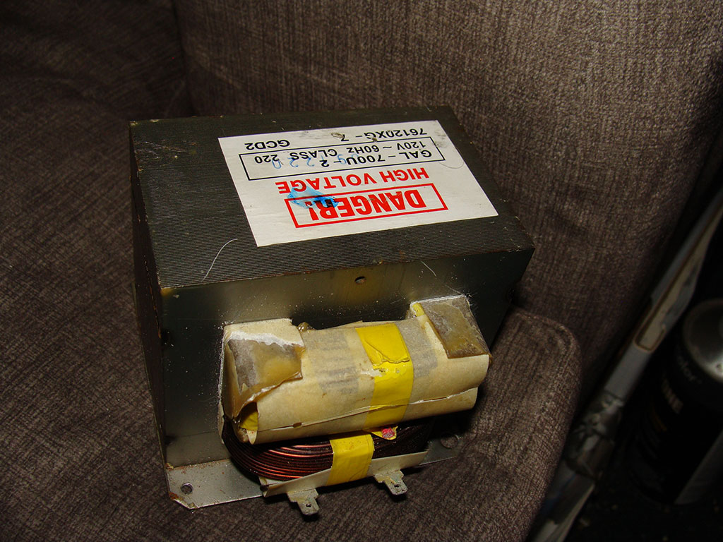 Take one transformer core
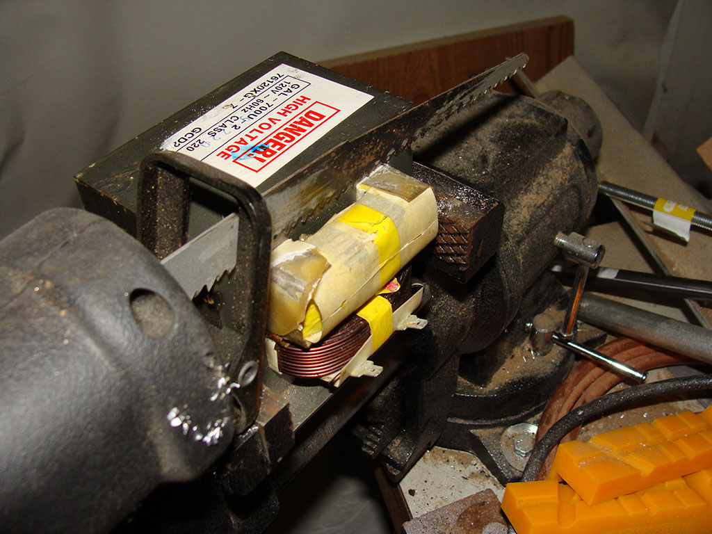
Trim off the excess secondary windings
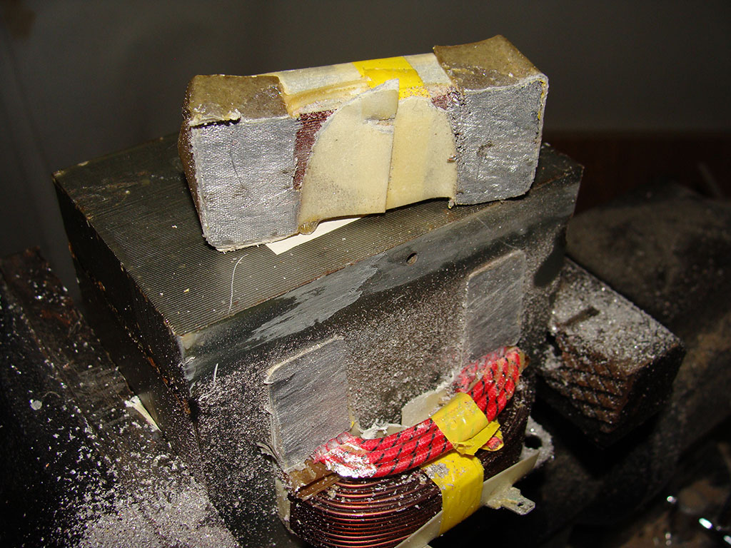
Place excess secondary windings aside for recycle (copper)
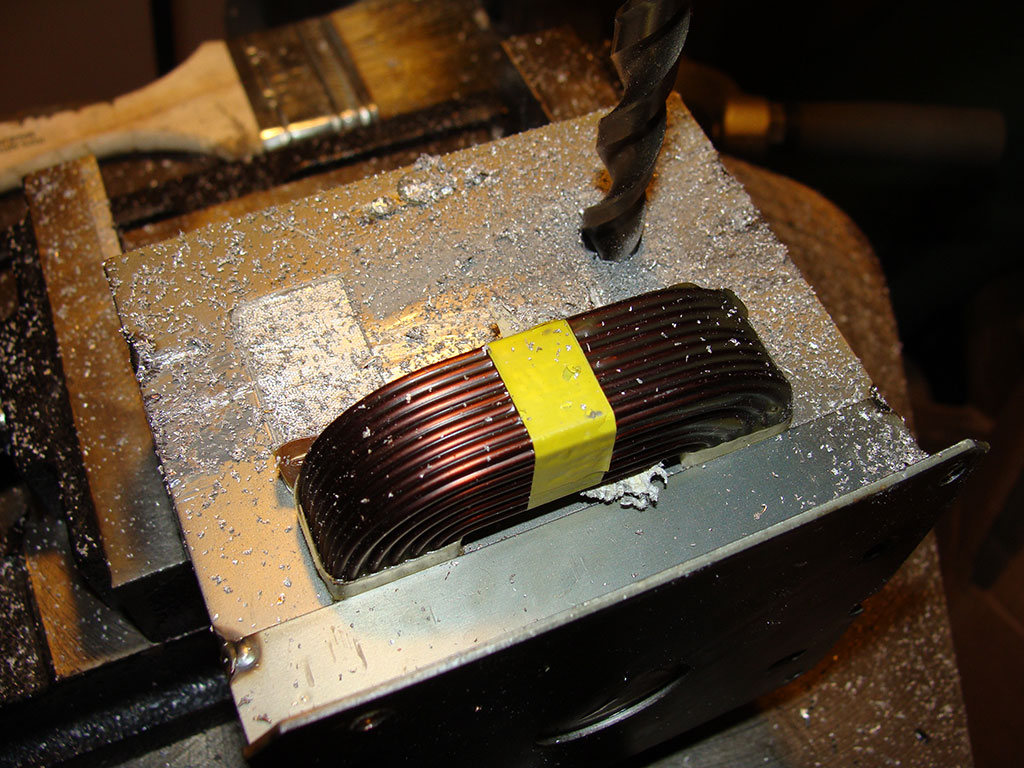
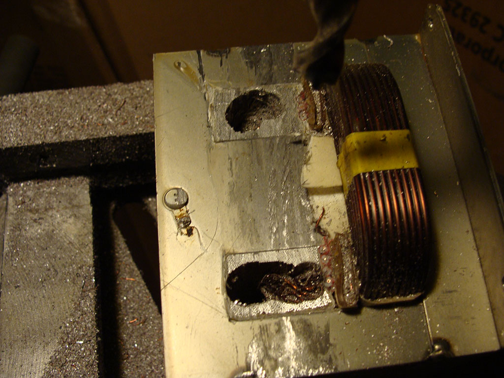
Drill holes in remaining secondary winding pieces
Knock the rest out with a hammer and screwdriver, etc.,
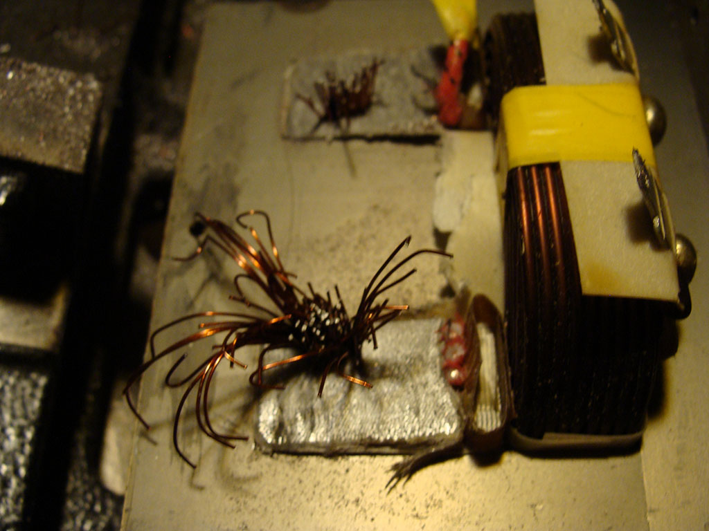
Clean out the core of all secondary winding pieces
Retape the core sections and re-install in transformer

Tape up the core with Kapton so it doesn’t damage the new winding
So this took care of the problem with the transformer for the filament. This thing no doubt has a ton of power, but I’m not sure how much. I know it is more than suitable to power the filament with plenty to spare. I might do some dead short testing on various objects this week if things get slow.
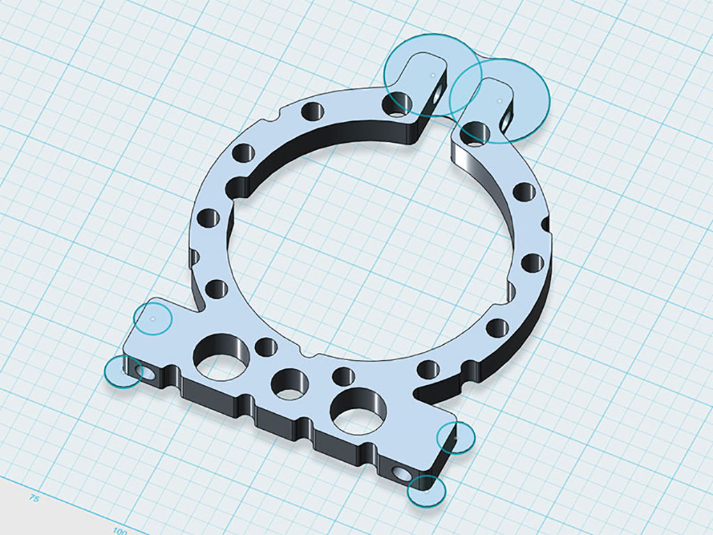
The final project for last week was that I needed to make some mounts for the big DC filter capacitors on the DC input section of the power supply. I haven’t figure out a case for this power supply yet, but I know I will need some way to mount the caps. I drew up some mounts in Autodesk 123D (the free version of course) and printed them out on my DIY 3D printer. The picture below is the 3D model I made in 123D, I tried to keep it light to reduce the amount of material that was going to be needed, and also tried to put a lot of holes in it reduce any long continuous paths which could induce warping of the object off of the heated print bed as it cooled. The ‘mouse ears’, as they’re called, also helped keep everything on the heated print bed.
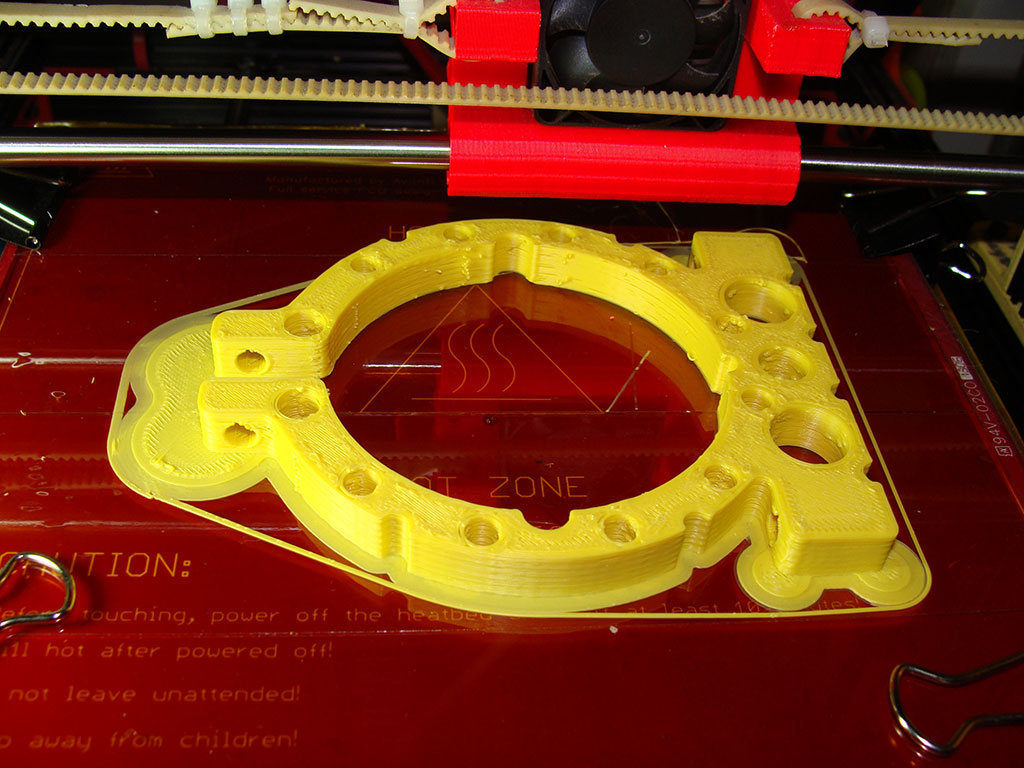
The 3D printed parts came out pretty good, they’re relatively large size. I had first tried to print them in Taulman Bridge nylon but was having some problems and so I switched over to yellow Makerbot ABS I had leftover from a long time ago. I store my filament in containers with desiccant but after a year I was a bit concerned. Amazingly there were no moisture problems and it extruded very nicely. I’ve always had very good luck with PLA and ABS with the new Bowden tube setup on my printer. I may have to switch to direct drive for the Taulman stuff, but I need to experiment more.
Here are a couple photos of the capacitors with the clamps around them, perfect fit! The clamps took about an hour a piece to print they ran with no intervention so I didn’t really notice it going on and could work on other stuff, that’s how it’s supposed to work, of course! The clamps will have a 6mm bolt through the top to draw the clamp tight around the capacitor. Hopefully these capacitors won’t reach the glass transition temperature of the ABS during operation or that might be a problem 😀
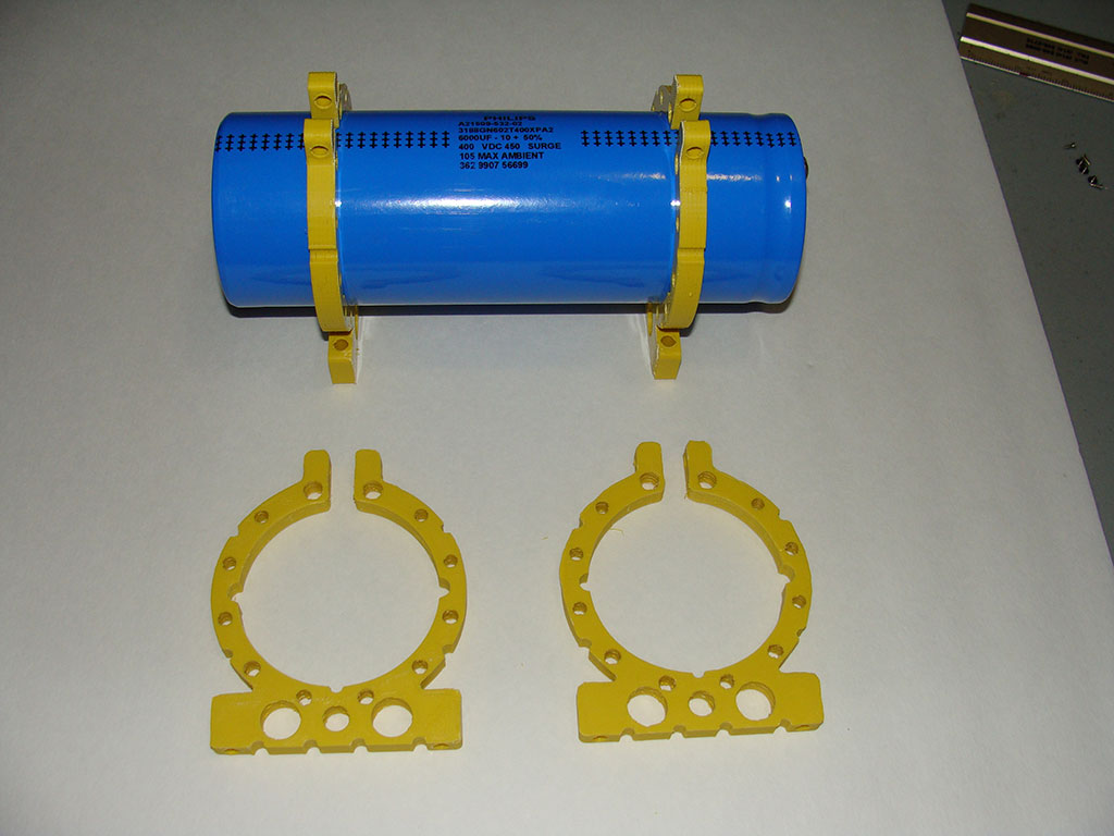
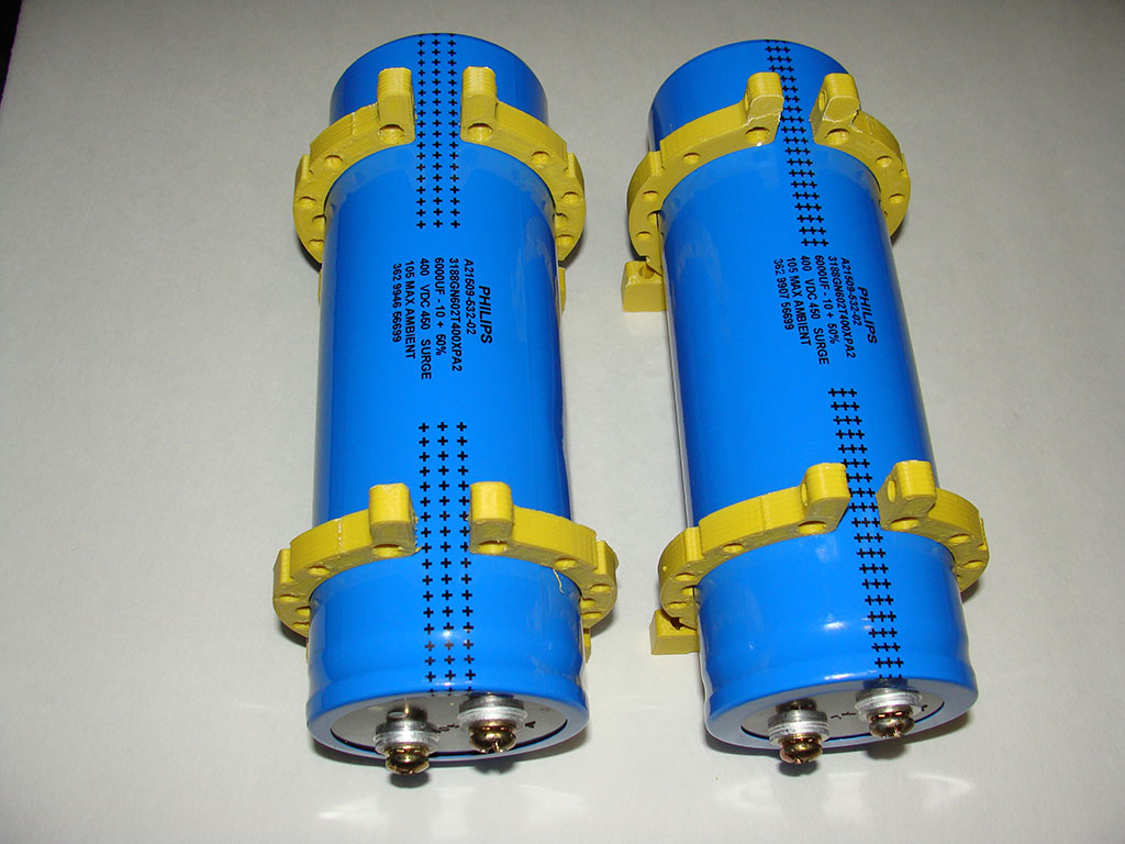
And here’s a photo of the capacitors sitting on the 3D printer for scale, they’re quite large at 3″ in diameter and about 10-12″ long. They’re rated 6000uF at 400V each. That wraps it up for this update, more to come I’m sure, I’m always trying to get more stuff moving on this project and I love logging about it.
I made a strange video about this week’s project progress report, it’s probably not for everyone but I thought I’d share it anyways.
Thanks!
Leave a reply to Large Switched DC Power Supply For Argon Laser Project Log 3