I’m in need of a large DC power supply for an argon laser and other projects. Argon lasers require tons of DC power to produce minimal amounts of output power, thus the power supply needs to be pretty beefy and durable. I also like building things and having projects to work on to help keep my sanity. Please keep in mind that this is me sharing my own experiences, it is not a ‘HOWTO’. Maybe you’ll be able to learn something from my successes or failures during the construction of this project or maybe not, no guarantees, but feedback is always welcome.
TL;DR; verson: I’m working on building a switch mode power supply from scratch using plans on the internet and trying not to kill myself. I’m slowly acquiring the items I need and will soon begin construction. Be afraid!
Longer version:
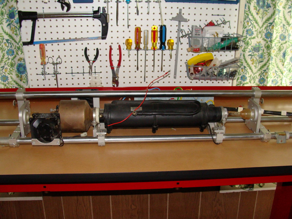
This project is a combination of a few things. The first is the big Meditec 3 watt argon laser tube that I’ve had sitting around. I want to try and fire that up and while I’ve been trying to find something like a Lexel 88 power supply for a while, they’re pretty rare or the prices are pretty ridiculous to deal with. While the tube it may just be too old to run, I’m having a hard time letting it go. I was going to originally just build a big resistance supply to power it, but I was told by someone who knows a heck of a lot more about their internals than I that it would probably be a bad idea since the Meditec tubes have a fragile cathode/filament which can be damaged by a supply that is not well current stabilized.
The second thing is that I want to build an arc lamp pumped Nd:YAG laser at some point, the linear arc lamps used require quite a bit of current as well so a big switched supply would come in handy for that
The third and not final thing, but the last which I’ll cover for now, is that I’ve always wanted to try building a switch mode power supply and getting into how that technology works. I could have gone for a pass bank design, which is simpler, but the switch mode designs are more efficient, a bit more modern and I really want to try to keep up with technology. And yes, I could go buy a 3 watt laser diode, but where’s the fun in that? I’m not really into light shows, I’m into electronics and lasers because I enjoy building and creating things.
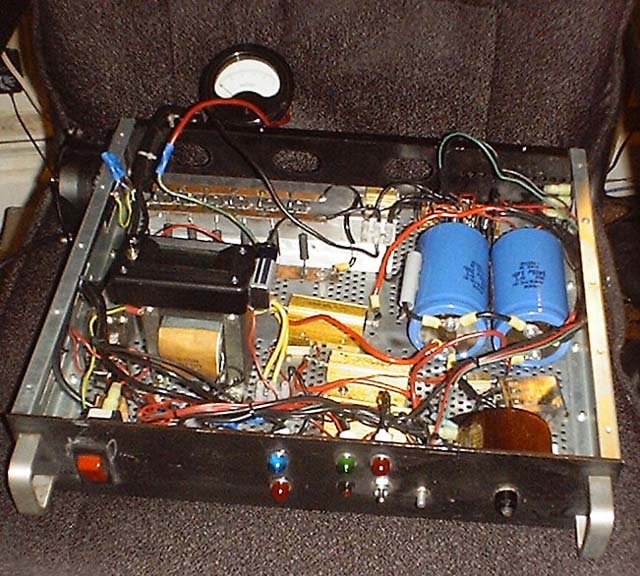
I have built a linear pass bank power supply for an argon laser before, but it was at much lower voltage and current. This is a picture of my old one, and it’s quite ugly. The new one will not be.
Rather than working from scratch which would be pure mayhem for someone like me who has electronics experience, but no switch mode design experience, I did some looking around online and found an example switch mode supply. The author lists it as ‘Universal Argon Switchmode Power Supply (30-250VDC, 30A)‘ which is based on the SG2525 regulating pulse width modulator. While I like the concept it is from 2004 and in need of some updating. A really modern version may use IGBTs, but I’m not to that point yet.
It’s somewhat of a modular design, allowing the stacking of MOSFET drive sections to increase the total amount of amperage the system can handle. A two module system is good for around 30 amps, which at 240 volts DC is ~7.2kW. A 3 stage system could be capable of over 10kW. Very tempting, but I’m starting with the basics first.
Some of the changes I plan on eventually making are as follows:
- Design PCBs for the smaller components
- Convert to surface mount components when possible
- Hall effect current sensor for feedback to the SG2525ADW
- Isolated drive for the MOSFETS instead of the current design with the HV floating drive electronics.
- Convert drive over to IGBTs which have lower on resistance and are more efficient.
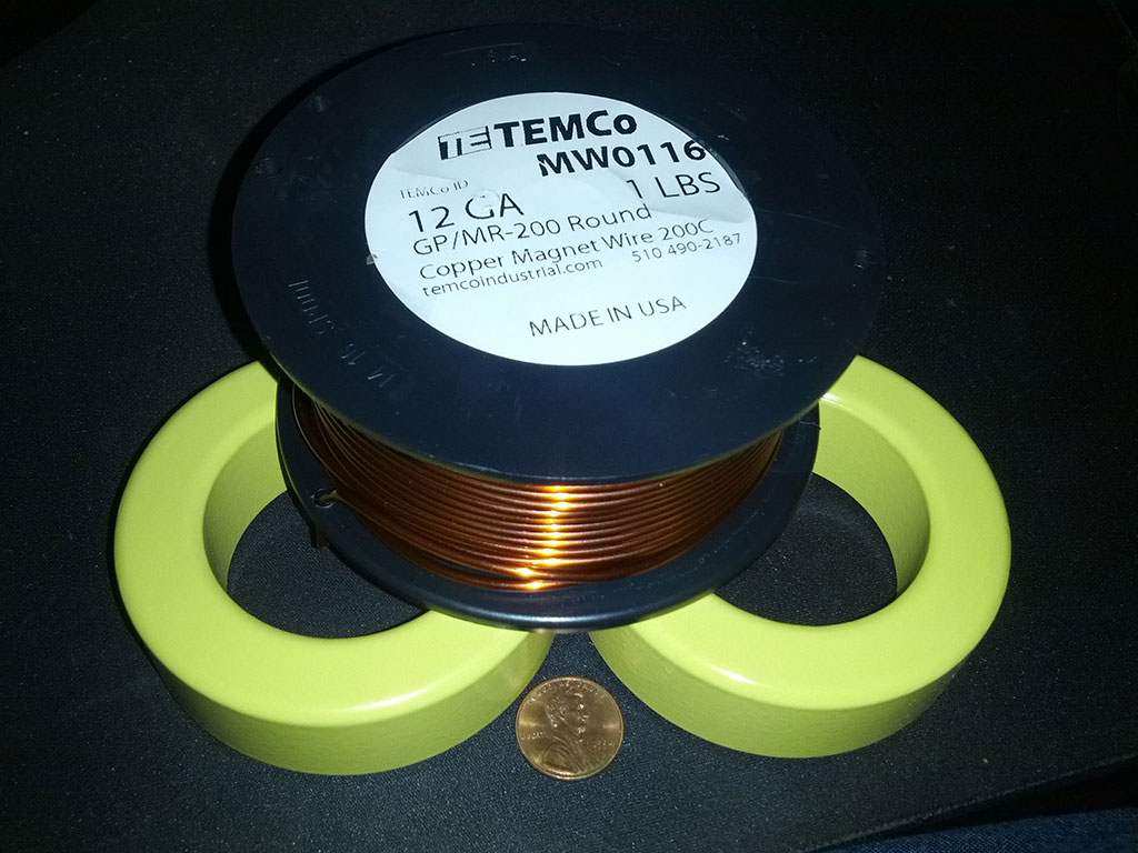
I’ve already got a start on this project. I needed two 360uH inductors for the two stage configuration. Because there is a large DC bias on the inductors, the author recommended molypermalloy powder based cores which don’t saturate as easily as iron cores. The models he mentions I was not able to find, originally, and so I settled on the iron cores, hoping they’ll work out OK. I bought some additional cores so that I will be able to stack them, if needed, to reduce core saturation under bias. Here’s a photo of the cores I’m attempting to use, they’re a Type 26 material 3″ in diameter and 1″ thick that I purchased from Amidon Corp (T300A-26). I ran the values of the core and wire through an inductor calculator and came up with 44 turns, around 3.3 meters of wire, needed for 360uH of inductance with 12 gauge copper magnet wire.
I bought the wire from TEMCo_industrial_power off of eBay, the prices are reasonable, they’re US based and it came quickly! They sell all sorts of industrial power stuff, nichrome, crimpers, heavy gauge wire, etc so worth a look if you’re doing similar projects.
The inductors don’t look machine made, but they’ll do I think.

Now, you’re probably asking me, how do you know if those are even the right inductance? Well, I don’t know at the moment. I’m going to try building an Arduino based inductance meter, similar to this one by Shadi Soundation and see what happens. The bigger question is, how will I know if the inductance will be the same once there is ~15 Amps of power flowing through the inductor… Well, I’m still working that one out, I need to read up on how to measure inductance when there’s a large bias current in the inductor without blowing anything up.
I figured that I would work on the hard to get items before worrying about alot of the smaller stuff so I also picked up some large aluminum electrolytic capacitors to use for the DC filter caps right off the rectifier. These are rated at 6000uF at 400 Volts DC. They’re a bit on the large side should provide plenty of capacity for the switch mode.
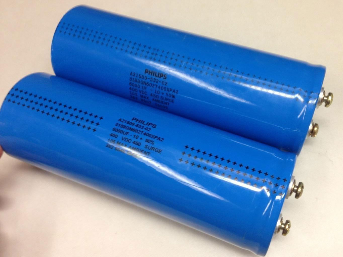

I couldn’t find any Philips documents which provide deciphering information for these capacitors, but since I’ve seen this exact part number being used as part of a pulsed power bank. I think for my purposes they will be fine.
I’ll be testing them before using them, hopefully they’re not dried out from being in storage too long, or haven’t been used beyond their lifespan. I have a Heathkit IT-11 and IT-28 coming in the mail that I can use to reform them and test them at full voltage for basic functionality. The capacitance meter on the fluke doesn’t go to 6000uF though.
Reforming seems like it’d be a fairly common practice for aluminum electrolytic capacitors, and it’s described in several places online. The IT series of testers are nice in that you can slowly notch the voltage up, and also reach the maximum rated voltage of the capacitors. Once I get these, I’ll make a post about them and using them to test and reform some capacitors.

Of course with any large capacitor you’re going to draw a huge inrush current when you first turn the switch or circuit breaker on. To reduce this surge I decided to remove the 50 Ohm 50 Watt resistor (R23 on the original schematic) and manual switch and replace them with an inrush limiter from Ametherm (AS35 1R040) on the HVDC side of the rectifier. It looks something like the picture below.
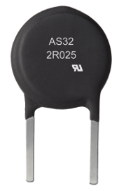
The current limiter basically starts off as high resistance, and as it warms up the resistance drops. If placed on the DC side: It starts at 1 Ohm which will limit the current inrush at 325VDC to to 325 Amps peak while the caps charge. This seems quite high, but without any limiter the inrush current would be HUGE (with a .01 Ohm resistance that’d be 32,500 Amps). Surge current could be further reduced by putting one on each side of the rectifier outputs, but a single one seems well within specifications from what I could tell.
The AS35 1R040’s max recommended energy rating is 800 Joules, these 6000uf 400VDC capacitors (at 325 Volts DC) store 317 Joules each, and 634 Joules total for the pair, under the max recommended of 800J and well under the 1600J actual failure point of the limiter. The limiter’s maximum continuous current rating is 40 Amps which is slightly higher than what I plan to be running the supply at normally.
Once I had those components out of the way I ordered a bunch of the other components I needed to build the circuits. My Digikey invoice when all was said and done was over 5 pages long. I have the schematic in Kicad right now and will be designing the first circuit board design soon. With OSHPark, it’s pretty easy to get a board designed and sent to you. I’m not worried about re-designing and making the revisions at a future date when I start making more modifications to the design. The expensive components are not on the circuit boards 😉
I also believe this needs more filtering on the DC input right after the rectifier and it wouldn’t hurt to have some extra current limiting protection. The Lexel 88 power supply uses a 6mH inductor for this purpose. I priced a 6mH inductor rated at 40 amps and it was over $180, way out of my price range for an inductor. The original design worked without it, bu it’s something I’ll have to think about.
Once this whole this is up an running in the basic configuration then I’ll worry about getting more fancy, on the fly over-current detection and short circuit protection would be awesome.
As always, I welcome input and ideas from folks regarding my projects. They are a learning experience for me, and it’s good to receive additional input and insights. If you follow me on G+ you’ll see updates on things that may not immediately make it here.
Leave a reply to Large Switched DC Power Supply For Argon Laser Project Log 1